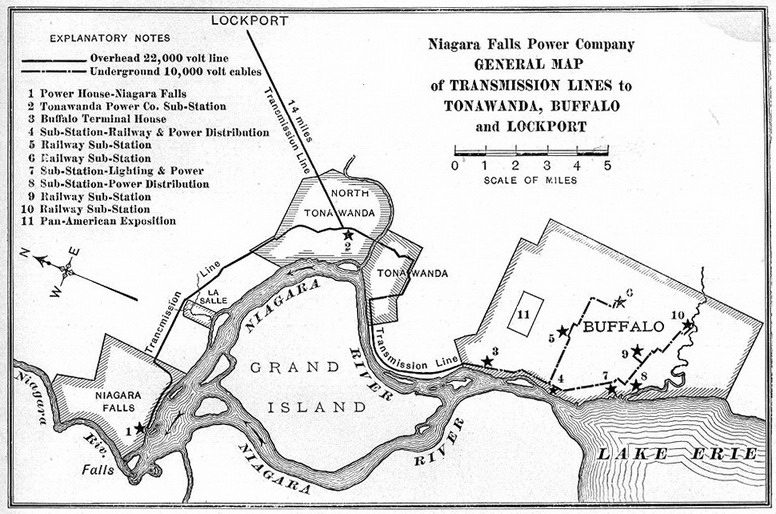
Niagara Power Transmission
Niagara Falls to Buffalo Power Transmission
Go To: Niagara, Lockport, and Ontario Power Co. -- M-3890
In the fall of 1894, a great challenge was raised to construct a 26-mile, 11,000 volt transmission line from Niagara Falls to Buffalo, NY. The power was contracted to be sold to the Buffalo Street Railway and the Cataract Power & Conduit Co. of Buffalo. This project was a very famous venture that received much publicity, since it would be the first successful harnessing of part of the enormous energy from this world famous waterfall. Both Westinghouse and General Electric were requested to submit bids to construct the hydroelectric project for the Niagara Falls Power Co. The Cataract Construction Co. was to be in charge of overall construction. Bids were soon submitted for all phases of construction. Apparently, there was some doubt about the feasibility of insulation. Nothing further developed regarding the construction of the power line until June 1896, when new proposals were requested. They decided to use cheap white cedar poles rather than iron poles. General Electric was granted the electrical equipment contract and The White-Crosby Co. designed the pole line. All of the technology was in place to build the 26-mile, "high-voltage" line, except for the insulators needed to support the conductor. Mr. J. G. White, from the White-Crosby Co., asked the question, "Are insulators such insurmountably weak links in such a chain, and is it not possible to get insulators that can be depended upon even when supporting wires under a pressure of 10,000 volts?"
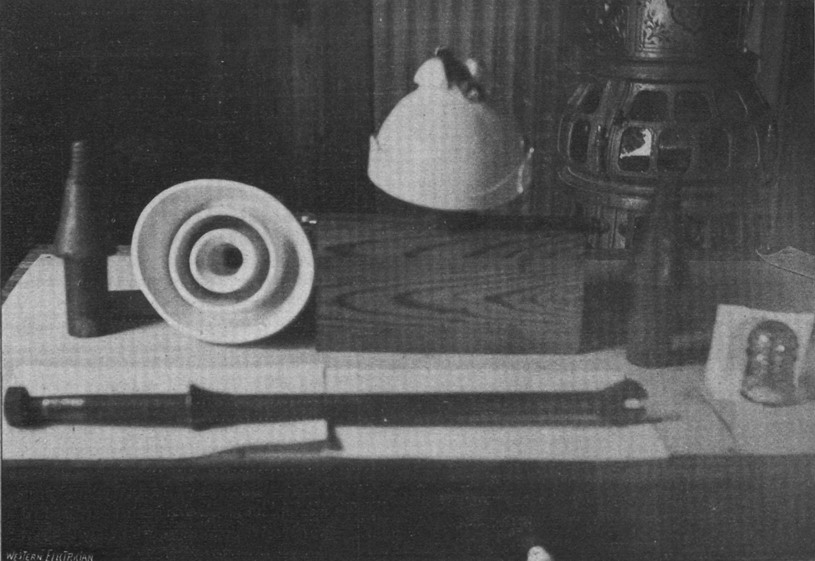
(Courtesy of Alan Drew, Northwest Lineman College)
The Search for the Perfect Insulator
In order for this very expensive project to be funded, it had to have a fixed date of initial operation (November 16, 1896), and a high guarantee of reliability. So intense was the concern over reliability that a complete spare circuit was built, and a very severe test was developed for the insulator. No other transmission line had been designed to ensure near total service reliability. Western power lines had already been installed at 10,000 volts and greater, but the weather conditions there were much drier. The call was made for insulators which would withstand a brine test of 40,000 volts. This severe test was required to ensure that the insulators would hold up under wet weather conditions, and to offer such a large degree of safety as to eliminate the chance of line outages due to the insulators.
The White-Crosby Co. received insulators from four insulator manufacturers, "...which were among the first six in this country in the production of porcelain for electrical use". The names of three of the four companies were never mentioned in various trade journals of that time, but we assume that they were Electric Porcelain & Mfg. Co., the R. Thomas & Sons Co., and General Electric, with the fourth company being Fred Locke, who was having his insulators made for him by Imperial Porcelain Works of Trenton, NJ. One of the two other companies who submitted sample insulators was probably Peru Electric Mfg. Co. We are not sure who could have been the sixth company. Fred's Imperial insulators were the only ones made from wet process porcelain, so he easily won the contract.
The only pin-type insulator known to have been made by Peru Electric Mfg. Co. was U-928B, but it was not made until around May 1898. It was made of one piece of dry process porcelain to compete with the 1898 Boch patent "glaze-filled" insulator made by R. Thomas & Sons Co.. Thomas. would have made a dry process triple petticoat insulator perhaps larger than U-923C, which they made for Fred Locke as early as 1895. General Electric was already producing the dry process U-744 by May 1895 for the Folsom to Sacramento transmission and the larger dry process U-935A for the 1896 Odgen to Salt Lake City transmission line. Dry process porcelain insulators proved inferior in tests performed on insulators for the Niagara line. Only the wet process porcelain insulator, U-937, made by Imperial Porcelain Works (Trenton, NJ) passed the severe tests.
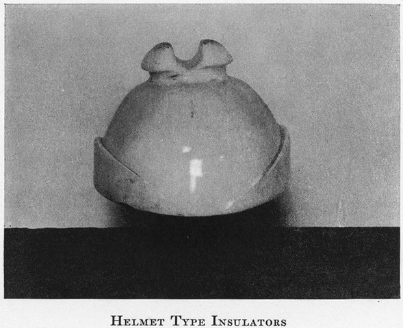
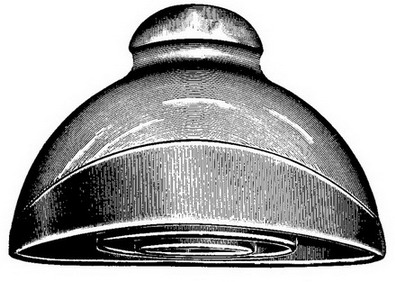
Photo of the Imperial Porcelain Works U-937 from the 1902 Cassier's Magazine.
The Niagara Type of insulator (U-937), the pins, a section of a double cross-arm, and the pin used to support the lightning protector wire on the cross-arms. (November 28, 1896 Western Electrician)
There are several trade journal articles, such as in the Electrical Review dated November 18, 1896 and December 16, 1896, and in the Electrical Review dated January 2, 1897, which stated that the White-Crosby Co. designed U-937. The first article stated that this style was manufactured by three separate companies. While we have not been able to learn much more than can be found in various conflicting trade journal accounts, a paper written by Mr. White in 1897, and presented to the members of the National Electric Light Assoc., indicated that each company submitted different designs. These articles were probably in error when they implied that the U-937 design was made by three different companies. There is no evidence to show that other porcelain companies submitted insulator samples that were similar in design. Further evidence is that Fred Locke eventually patented the novel features of U-937, but the patent application was not submitted until December 16, 1896, just one month after the Niagara-Buffalo line was put into service. We do not know why he waited so long to apply for the patent unless he was waiting for permission from the White-Crosby Co. to submit a patent, or he was very busy helping Imperial produce the order. The later was probably true. The patent for U-937, No. 590,806, was granted on September 28, 1897. U-937 was oval shaped with eave troughs one each of the long sides to drain rain water away from the crossarm.
Fred Locke's winning insulator, U-937, had a couple of very unique features. The conductor groove was oriented in such a way as to allow the downward sloping oval ends of the insulator to extend past the crossarm. Such an alignment would have first required that the lineman firmly mount the insulator on the pin, then turn the insulator and pin around on the crossarm to properly orient it, all before putting the nail in the crossarm to secure the pin. On either side of the insulator was a ridge, running parallel with the conductor and curving downward to near the ends of the oval. The purpose of the ridges was to direct rain water away from the crossarm; but, this was only half the story. The designers of the power line wrongly believed that there was a possibility of forming heavy layers of ice on both the line and insulators during winter storms, which would result in severe damage and power outages. That was the sole reason for the short pole spacing. The oval design of U-937 was an effort to alleviate this problem on the insulators. They hoped that rain water, during freezing weather, would form icicles along the oval drip edge of the outer skirt, in such a way as to allow the icicles to hang down away from the crossarm. This would prevent the icicles from contacting the crossarm and forming a path for leaking electricity to short from the insulator to ground. The problems with ice never materialized, as the current kept the line and insulators warm enough to prevent a build-up of ice. During wet weather, the deep grooves of the triple petticoats helped to reduce electrical leakage to the pin. As you might guess, the narrow ridges were of little benefit in directing rain water away from the crossarm, and the non-symmetrical shape of the insulator would have produced an electrical imbalance.
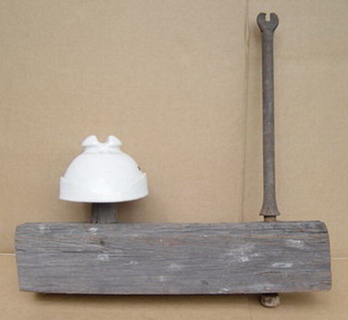
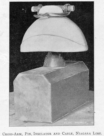
U-937 on original crossarm with original forged iron support for a wire that provided protection from lightning. The iron support also prevented a conductor from dropping off the crossarm if the insulator was damaged.
Transmission line pole from Oct. 28, 1896 Electrical Engineer. Note the forged steel supports on the top crossarm to hold a wire for lightning protection.
U-937 from June 1897 American Electrician (left) and January 2, 1897 Electrical World (right).
U-937 on section of original crossarm from January 22, 1898 Electrical World.
Curve on the 11,000-volt Niagara Falls to Buffalo transmission line from June 5, 1897 Electrical World.
![]()
Repair wagon and first Niagara Falls to Buffalo transmission line. This photo also appeared in the 1902 Cassier's Magazine. (Photo Courtesy of Niagara Mohawk Power Corp, from Richard Peterson's Photo Collection.)
The Electrical Review, dated November 25, 1896, stated that earlier in the week, just before the startup of the power line, a problem developed with the insulators. They soon realized that a sufficient quantity of Imperial insulators were failing the electrical test, which would create a shortage of insulators, and prevent the completion of the power line before the November 15th deadline. About twenty-five to forty percent of the Imperial insulators were failing the 40,000 volt brine test; however, this percentage decreased in the last shipments. The White-Crosby Co. at once telegraphed three of the four insulator manufacturers to request that they rush shipment of all of the insulators on hand of the design they had submitted. After passing a modified test pressure of 20,000 volts, a sufficient quantity of temporary insulators from two of these companies was approved to make up the quantity that Imperial could not produce. The last of the temporary insulators was removed in February 1897 and replaced with Imperial insulators. The Electrical Review, dated December 16, 1896, summed up the situation as follows:
...the porcelain insulators were supplied by three firms. The best of the lot were those sent by the Imperial Porcelain Works...; but owing to the fact that this concern could not turn out enough insulators, made with the unusual care required for this special use, the product of two other companies was temporarily utilized until the Imperial Works could finish the order.
These temporary insulators were probably General Electric's dry process U-935A, and the Thomas three-shelled experimental insulator. There is little chance that any of the temporary insulators were left along the line, so we will never know what styles they used, or who supplied them. Only Imperial insulators were made by the wet process, and their insulators were ultimately the only ones that passed the required severe electrical test. The Niagara-Buffalo line was submitted to a short test on November 15, 1896, and officially put into service at 12:01 a.m. on November 16, 1896. There were no failures of the Imperial insulators in the first six months of operation.
Specific information could not be located about the use of another Imperial insulator on the Niagara line, other than a reference that a round style of Imperial insulator was used at the same time as U-937. This style was U-934, as confirmed by a number of these having been found along the line in the very early 1970's. Illustrations of this insulator, in profile only, have appeared in various sources. This round variety was called, Type "C", whereas the "Spanish helmet" U-937 was called the "Niagara Type". Classic insulator hunters should note that the Electrical World, dated October 9, 1897, stated that U-937 was also used on the Lachine Rapids transmission line. This line was constructed in 1897 from Lachine Rapids to Montreal, Quebec, but it only operated at 4,400 volts over the six-mile length. The insulators used on that line may have been rejected insulators from the Niagara project.
The June 16, 1897 Electrical Engineer hinted at the use of another Imperial insulator that was evidently used to complete the order for U-937. The test failure rate was so high that Imperial had difficulty in supplying all the oval insulators required by the specified time. Imperial probably requested the change to U-934 because the round style was easier to produce; hence, they could produce faster than U-937. The following paragraph from this trade journal hinted at the use of Imperial's U-934:
It is, however, worthy of special note that since the last of the temporary insulators were moved from the line, there has not been one minute's suspension of current supply due to defective insulators. During this time, some three or four months, three insulators have been replaced, none of these [U-934] being of the oval type [U-937]. Two of these three had been broken while being put in place, and the third was broken by a stone or other missile. In all three cases only the outer petticoat was broken, and the insulator continued to do satisfactory service until such time as it could be replaced without affecting the operation of the line.
The fact that two of the three broken round insulators were "broken while being put in place" indicates that they were made and installed before the line began operation. The approved Imperial insulators (both U-937 and U-934) were is such short supply that necessity required even damaged Imperial insulators be used. That indicates to me that the temporary insulators made by the two other companies were considered inferior to broken Imperial insulators! What better testimony could Fred and Imperial get, except that U-934 was not Fred's design.
In 1986 Jack Tod told me a story about obtaining specimens of these two Niagara insulators. Before 1972, Jack knew of only one U-937 (in Frances Terrill's porcelain insulator book), and it had a broken skirt. He said that he had a table at the Ithaca, NY show in April 1972. A mint U-937 showed up on the table of the show hosts. They directed a man to Jack, and he went out to the man's car. When the man opened the trunk of his car, Jack said, "my eyes nearly fell out of their sockets". The trunk was full of "those rare and infinitely desirable U-934 and U-937 insulators". The man was a lineman, and he had personally rescued these from the Niagara line. Jack couldn't recall the details, but these insulators came from a specific terminal location that was being rebuilt, and the man got all that were there which were still in service at that time! The man had eleven U-937's and possibly the same number of U-934's. All were in mint condition, or nearly so, and complete with a natural, light patina of dirt and smoke, acquired by 75 years of service. The man was asking $50 each for the U-934's and $75 each for the U-937's. Jack only got one U-934 and three U-937's, but started "kicking himself" for not finding some way to go in hock with friends at the show, in order to obtain all of those super goodies (Such things that dreams are made of!). So, only about a dozen of each style have been recovered over the years, but more U-934's may be in collections. A number of U-934's surfaced in the mid to late 1970's, which were used on the Niagara Falls to Buffalo line. I acquired three with different markings. One of them had the Imperial crown marking without a date, and the other two had either one or two of the #1 Imperial marking without a date. At least one is known from the Niagara line with Imperial mark, crown logo, and date. Two others from that line have two Imperial marks with a date. One is dated 7-1-97 and the other 8-1-98.
A small number of Imperial U-934s have been found in British Columbia. These insulators have only two marking variations. Most have the Imperial mark plus the crown logo with manufacturing date. Only one is known with the Imperial mark and date (no crown logo) and one known with two Imperial marks and date (no crown logo).
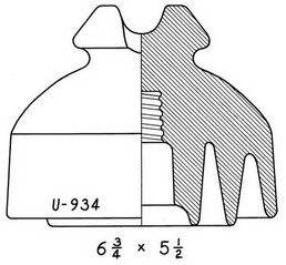
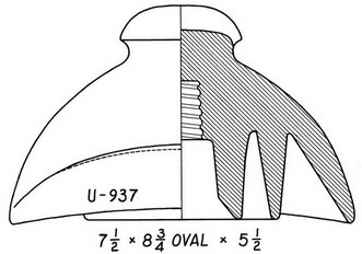
Photo was taken in the 1960's. All the white insulators are Imperial U-934 except for one U-937, which is on the end of the first crossarm and closest to the camera. (Courtesy of Bill Kuhar)
The First Pole Line
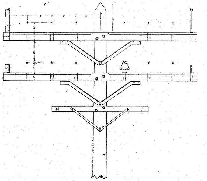
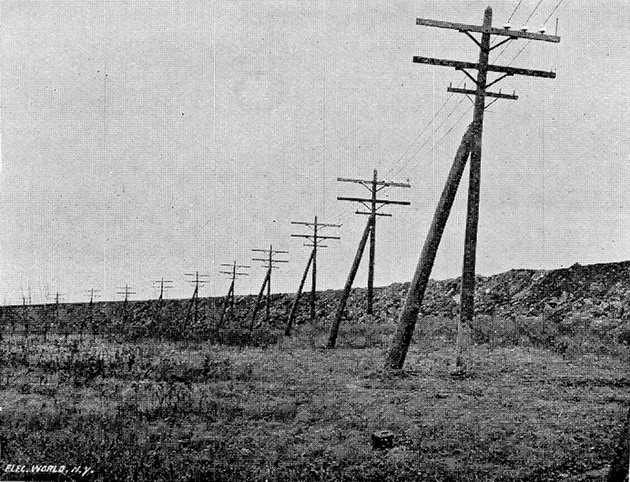
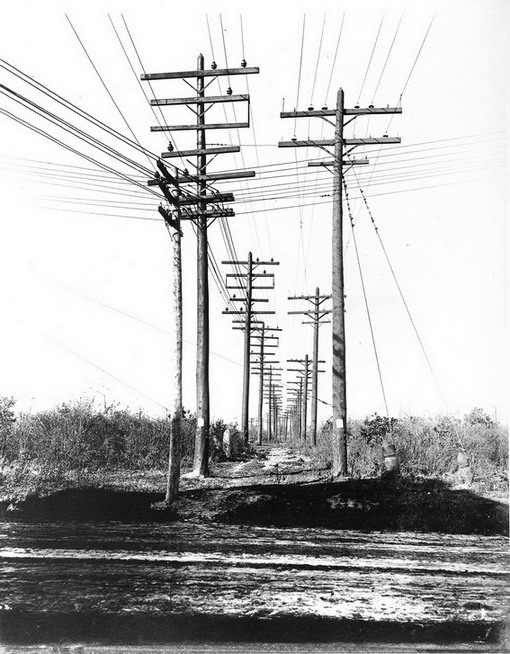
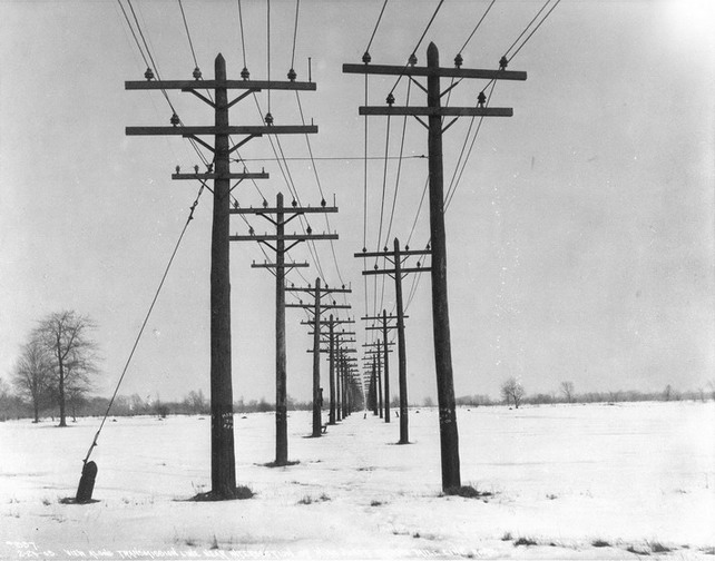
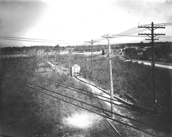
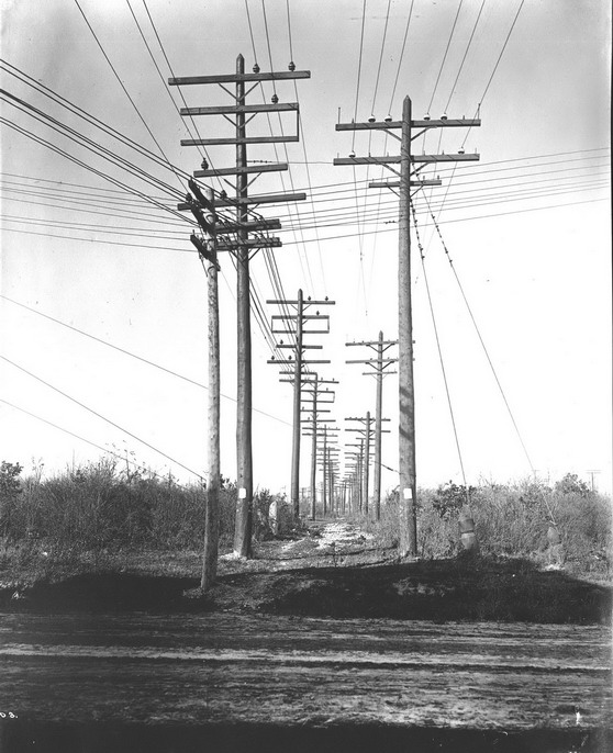
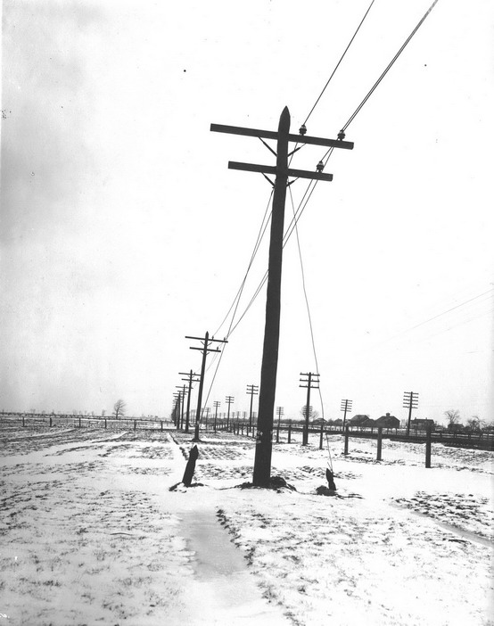
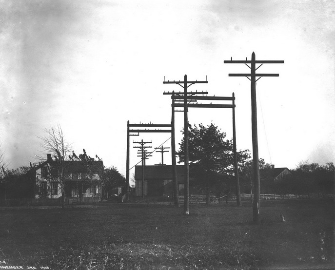
The original Niagara-Buffalo line was actually two separate circuits, one circuit on each side of the pole. Two crossarms were installed, but only the top crossarm was used initially. The second crossarm was to be used later to add two more circuits. Each of the three conductors, which made up one circuit, were place side-by-side, just 18 inches apart. This arrangement, with three conductors on the same horizontal plane, and only 18 inches apart, soon proved to be a mistake. Mischievous boys would repeatedly short-circuit the line by throwing short pieces of wire across the conductors. They were often successful in laying the wire across two or more of the conductors, which would result in a spectacular blaze that would travel along the line, lasting until the power was cut off at the falls. To solve this problem, the conductors were rearranged in a triangle pattern, one circuit on each side of the pole. One conductor was placed on the top crossarm and two on the crossarm below, making the conductors 36 inches apart and much more difficult to lay a wire across. There were six insulators on each pole (two circuits), and about 2,100 poles were used along the 25 miles of line. The last 4,000 feet of the line was underground, in conduits. So, about 13,000 insulators were used.
![]()
U-966 (left) Type "E" and U-934 (right) Type "C"
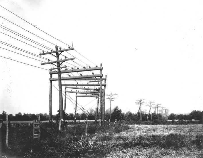
The Second Pole Line and the Type "E" Insulator
In late 1900, work was started on a second pole line. This line followed alongside the original line, until just near the end where it took a slightly shorter route. This new line was designed for 22,000 volts. A new insulator was designed that would be stronger mechanically. The insulators on the original pole line used a standard one-inch wooden pin. These new insulators were designed for a 1-5/8 inch wooden pin, since the pole spacing was changed from 70 feet to 140 feet. The pole spacing was increased to save costs. Originally it was thought that a shorter pole spacing would be needed to allow for the extra weight of one-half inch of ice, that was expected to form on the conductor. However, it was learned from experience that ice never built up on the conductor since the heat generated by the electrical current kept the ice from forming. The insulator design chosen was the much stronger U-966 made of two parts glazewelded together. These brown glazed insulators were made by R. Thomas & Sons Co., as evidence by broken specimens found along the line. A few near mint to mint brown glazed insulators of a similar style made by Imperial, U-966B, have been found along the Niagara, too. Maybe both insulators were used for the original construction. A few New Lexington U-966A's have been found around iron mining operations in Upper Michigan, but we do not know if this style was used on the Niagara line. If so, they would have been replacements and would have been made after the New Lexington was formed in 1903. The U-966 and U-966B insulators were called Type "E". This second line was put into service on April 1, 1901.
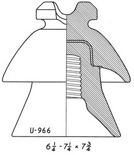
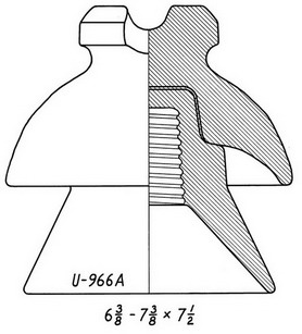
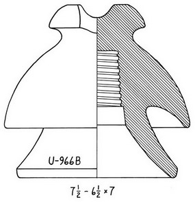
U-966 was made by R. Thomas & Sons Co. U-966A was made by New Lexington High Voltage Porcelain Co. U-966B was made by Imperial Porcelain Works.
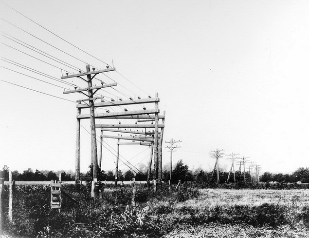
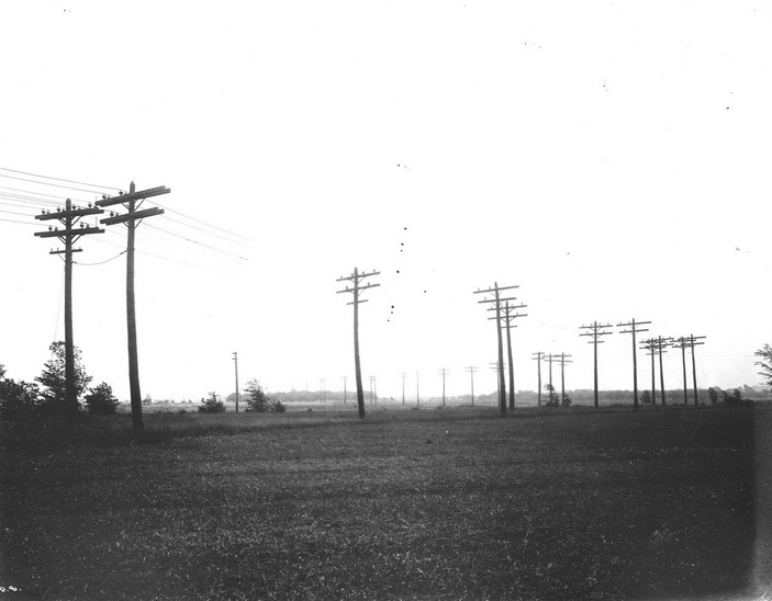
Original pole line is on the right with two circuits supported on Imperial U-937 and U-934. The second pole line in on the left with two circuits supported on Thomas U-966.
Both pole lines at this location used Thomas U-966.
Another location showing all wire supported on Thomas U-966.
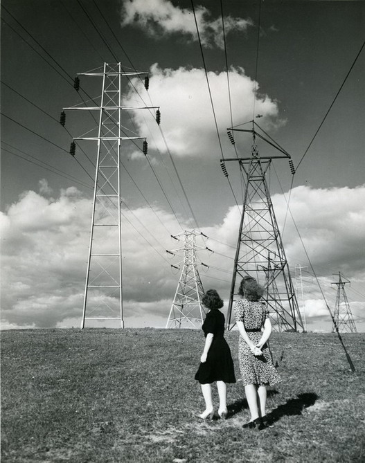
Large high voltage towers with modern suspension disk insulators marked the original right-of-way in the 1950's. (Photo Courtesy of Niagara Mohawk Power Corp, from Richard Peterson's Photo Collection.)
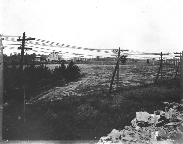
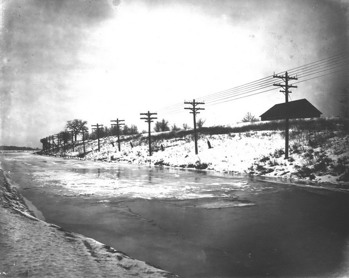
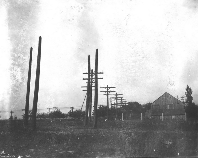
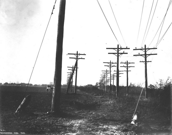
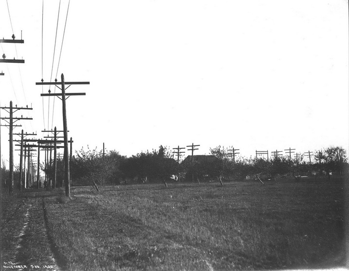
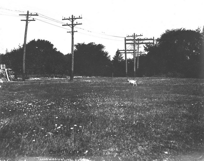
Below are many more photos of the original Niagara Falls to Buffalo line. Just click on the thumbnail photo to see a larger image. (Courtesy of the Smithsonian American History Musuem)
Go To: Niagara, Lockport, and Ontario Power Co. -- M-3890