Niagara Power Transmission
Niagara, Lockport, and Ontario Power Co.
Go to: Niagara Falls to Buffalo
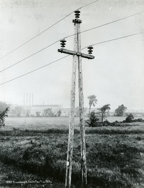
On July 7, 1906, a great power line was put into service that proved to be an unexpected learning experience. This was the 160-mile long line of the Niagara, Lockport, and Ontario Power Co. The company did not own the power generation equipment but was strictly a transmission company only to supply power over a wide area of northern and western part of New York east of Niagara Falls. The power line transmitted power at 60,000 volts generated by the Ontario Power Co. from the Canadian side of Niagara Falls. Water was taken from the Niagara River and redirected through underground shafts to a power station located at the bottom of the cliff near the foot of the falls. The Niagara, Lockport and Ontario Power Co. took delivery of the electrical power at the international border in the middle of the Niagara River. The line ran mostly on steel towers 16 miles east to Lockport then 57 miles to Mortimer near Rochester, 10 miles to Fairport, and 71 miles to Syracuse. Additional lines carried power in the vicinity of Buffalo. In 1907, a duplicate line was erected running parallel to the first. The power line and all of its branches totaled 400 miles and contained 7,000 steel towers and 23,000 insulators.
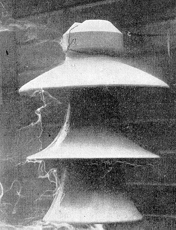
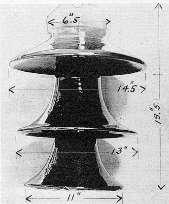
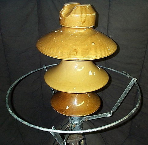
Photo (left) from the 1906 Journal of Electricity Power & Gas showing a Thomas M-3890 being tested. Photo (right) shows dimension of M-3890.
The insulator used on the line, M-3890, was designed by Ralph Mershon to prevent flashover and cemented to a steel pin. The middle and bottom shells of M-3890 had upward curving skirts commonly referred to as “lily-shell” design. Each of the three insulator shells was tested at 75,000 volts for a duration of three minutes before assembly. The completed insulator was not tested. The dry flashover voltage was 195,000 volts and the wet flashover voltage was 120,000 volts. This was considered a great safety factor and supposedly suitable for all conditions.
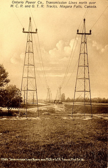
Photo of the power line taken on March 24, 1906, in Canada between the power plant on the Canadian side of the Niagara gorge and the water crossing towers where the lines span the Niagara River. (caption courtesy of Mike Spadafora)
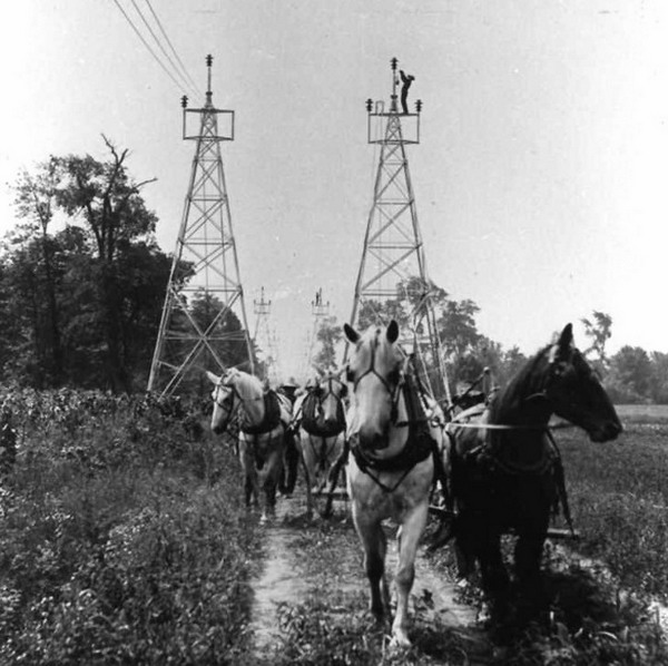
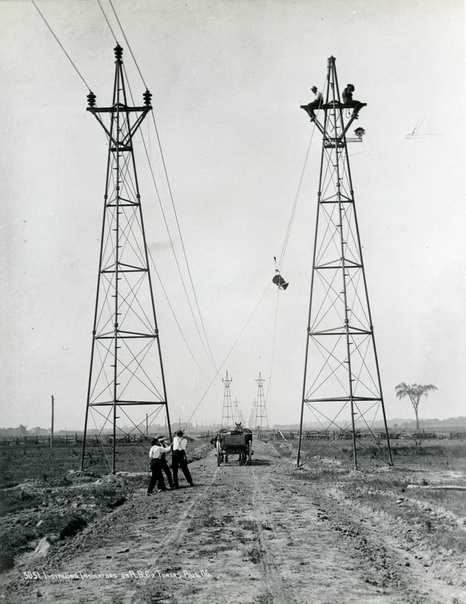
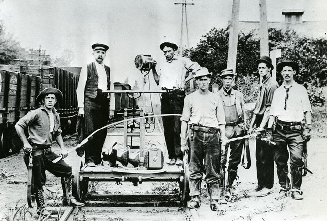
Stringing conductors along the towers.
Trouble with the insulator soon developed. Lightning was particularly severe in the area and resulted in many damaged insulators. Direct strikes by lightning were not the only source of damage. Lightning striking in the vicinity of the power line induces an electrical surge resulting in insulators experiencing flashover or puncture. Puncture is where the electrical voltage is so great that it pierces a hole through the porcelain shells down from the cable groove to the steel pin. Often the hole is so minute that it is difficult to see. Curiously, some insulators were also damaged even though they were not subjected to flashover. The damage was exhibited by one or more broken shells as if a hammer struck the insulator several times. In particularly severe cases only the insulator crown survived. Even lightning strikes 500 feet away caused damage and puncture. By the end of 1906, thirty-five insulators had been damaged out of 12,000 insulators installed during eight different storms. The insulator on top of the tower was usually the most severely damaged. Naturally, electrical service was disrupted.
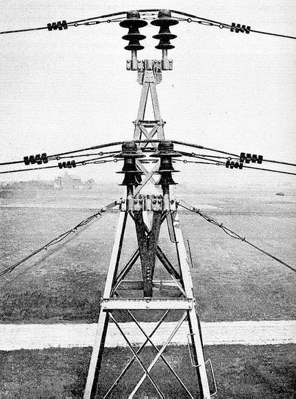
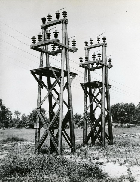
M-3890's on double crossarms.
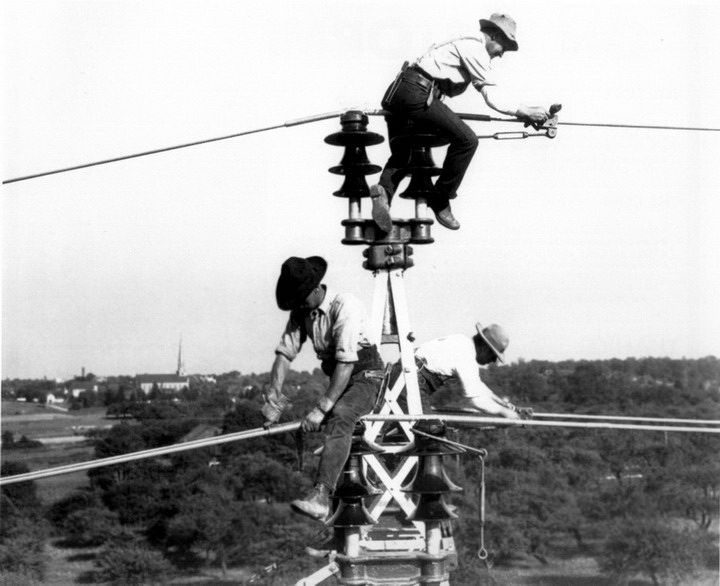
Linemen attaching conductors to M-3890's. (Courtesy of Alan Drew, Northwest Lineman College)
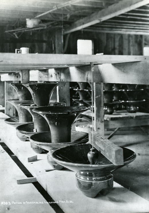
Cementing shells for M-3890's. Photo was taken on March 21, 1906. (Photo Courtesy of Niagara Mohawk Power Corp, from Richard Peterson's Photo Collection.)
Corrective action was taken before the 1907 lightning season. Arc relief gaps were installed on selected top insulators spaced about 2200 feet apart. The arc relief gap was a pair of curved metal rods called “arc horns”. One was attached to the crown of the insulator and the other was attached to the pin under the insulator. The purpose was to allow the electrical surge from a nearby lightning bolt to jump across the arc relief gap to ground rather than finding a more difficult path across the surface of the insulator, which so often resulted in damage to the insulator. An experimental gap of six inches was set which would allow an arc to jump across at 70,000 volts. During the 1907 lightning season, it was quickly learned that the arc relief gaps protected only the insulators on which they were installed. About 25 per cent of the 750 arc relief gaps discharged one or more times. Most of the insulators damaged in 1907 had been punctured. In 1908, 114 of the 226 insulators damaged had been punctured.
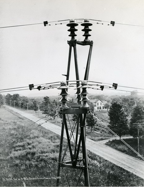
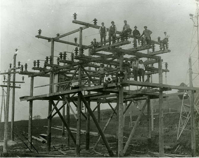
This switch and bus structure was located between Weedsport and Auburn, NY. The line south of this point is still in service, but the line north was removed long ago. In the background you can see one of the towers from the Rochester-Syracuse main tower line. The photo facing northeast also shows the incoming link line from the north that interconnects the main wood pole "A" frame line along the West Shore Railroad with the main Rochester-Syracuse line. The steel tower at the far right has gray-glazed VICTOR M-4338's. This would indicate the photo was made after 1909 and likely when an upgrade or removal of this structure was taking placed. (caption courtesy of Mike Spadafora)
(Six photos above Courtesy of Niagara Mohawk Power Corp, from Richard Peterson's Photo Collection.)
After the 1908 lightning season, Nicholson arcing rings were installed. It consisted of one large ring mounted just above the bottom of the insulator and a smaller one around the tie-wire groove. This would allow a power arc to jump down to the larger ring and on to ground without damaging the insulator. Lloyd Nicholson was granted two patents in 1910 for arcing rings to be used on multipart porcelain insulators and a third patent using them on suspension insulators.
It was discovered experimentally that the intense heat of the power arc was responsible for damaging the insulator. This was particularly concentrated and damaging when the power arc transferred the intense heat up through the center of the insulator by means of the pin. The lower Nicholson arcing ring directed the power arc upward preventing damage to the insulator.
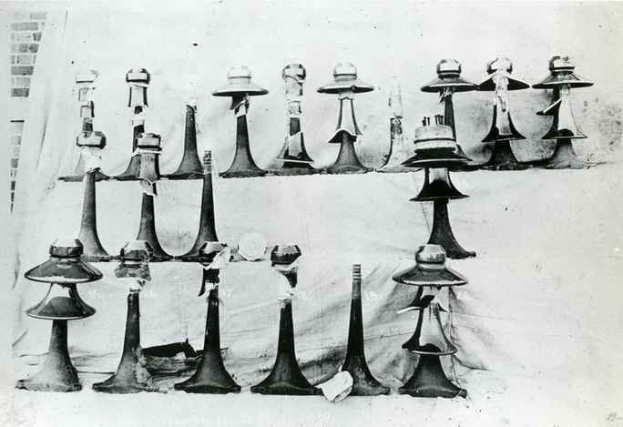
A selection of M-3890's damaged by lightning. This photo appeared in the March 31, 1910 issue of the Journal of the AIEE. (Photo Courtesy of Niagara Mohawk Power Corp, from Richard Peterson's Photo Collection.)
Before the 1909 lightning season, 11,000 insulators were removed from 195 miles of line and tested dry at 195,000 volts. Almost 40 per cent of the insulators failed the test. Almost 82 per cent of insulators that failed the test failed because of the bottom shell.
A new insulator was designed to replace the top
insulator on each tower. This
insulator was M-4338 made by Locke. It
has a unique cross-top design and a recessed fourth skirt to aid in resisting
puncture. This new design was six
inches shorter. It was designed
shorter than the top skirt diameter so it would flash over before building up
sufficient power to cause puncture. This
novel design setting the ratio of the top skirt diameter to the overall height
of the insulator at less than 1, became standard design practice during the
1910’s. In addition, the shorter
porcelain shells created a more balanced voltage distribution around the
insulator reducing the electrical stresses on the insulator.
The parallel power line was not fitted with arcing rings or M-4338 so a
comparison could be made in the 1909 lightning season.
The non-improved parallel line had 54 insulator failures compared to only
one failure on the improved line. The
Nicholson arcing rings and M-4338 on top proved a successful solution to
lightning damage.
There are about 2-4 known gray-glazed specimens of M-4338, which bear the incuse “VICTOR” marking. No whole specimens of M-3890 have ever been located. Mike Spadafora has expertly "kitsulatored" (piece together from broken fragments) about 12-15 unmarked light tan New Lexington M-3890's, about 3 with New Lexington marking (NEW LEXINGTON, O.), about 4 with marking NEW LEXINGTON, O. and Oakman patent marking PATENTED JUNE 17, 1890, four unmarked Thomas specimens with pretty orange/mustard glaze and three with darker glaze.

Thomas version of M-3890.
New Lexington M-3890 with refurbished Nicholson Arcing Ring.
Go to: Niagara Falls to Buffalo