Fred Locke: Page 2
|
M-2795 with "303" marking |
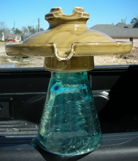
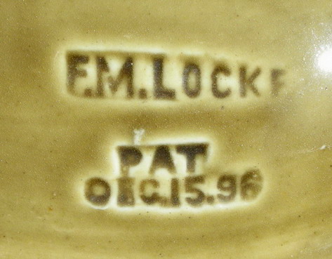
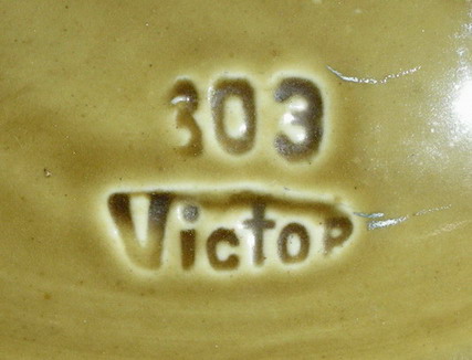
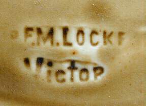
This is the only known whole specimen of M-2795 with the "303" marking. It was in the collection of Tim Wood for a number of years. The various Fred Locke markings have been given reference numbers. A complete listing of the reference numbers as they apply to multipart insulators can be found in my book, 2nd edition of Multipart Porcelain Insulators. The "303 / Victor" marking is #1-5c and the F. M. Locke marking shown above is #1-5. The M-2795 was developed in early 1900 for the Bay Counties Power Co. (from Colgate Powerhouse) and the Standard Electric Co. (from Electra Powerhouse) transmission lines in northern California. Originally, M-2795 was cataloged as Fred Locke's No. 303. When his next catalog was published in late 1900, the catalog number had been changed to No. 316. The change was to accommodate his new Victor series of multipart insulators. A complete history about the development of M-2795 and the Victor series can be found in my book, Fred M. Locke: A Biography.
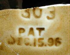
In 1999, Howard Banks found 3-4 badly broken M-2795 tops in southern Oregon with a "303" marking. At least one had a slightly different "303" marking that has been assigned reference number #1-5a. Likewise, the marking on the opposite side was different, too. It is marking #1-5b. Both markings are shown below.
The photo below shows the bottom of the "303" M-2795 with the glazewelded collar and the original sulfur cement.
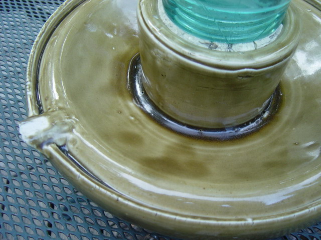
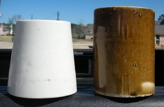
A brown cylindrical pin base was first used with M-2795; however, one photo in a trade journal shows a white porcelain pin base. There are only 3 brown pin bases known. There are only 2-3 white pin bases known and they were all dug in what is known as the "Fred Locke attic dig" in Victor, NY. The white pin base is 4-1/4" tall and the brown pin base is 5" tall.
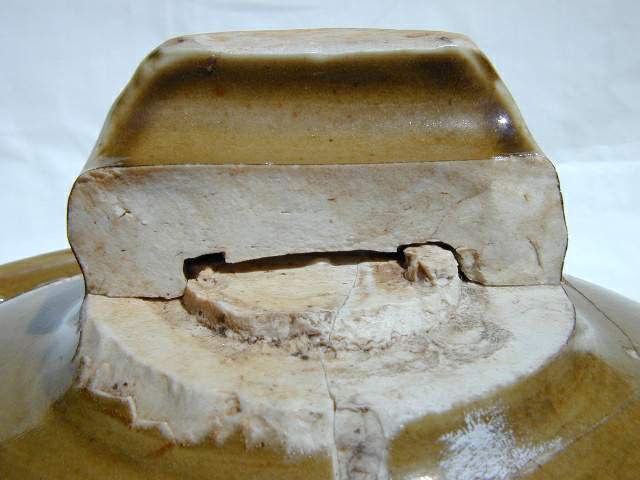
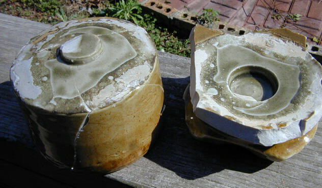
Howard sent me two pieces of M-2795 that show how the crown was put together. We suspected that the crown was hand applied to the top shell similar to how handles are applied to a teacup. Several specimens have been found which had the crown cleanly sheared off. It was obviously not glazewelded but rather applied by wetting the clay crown, fitting it on round projection formed in the center of the top shell, and then smoothing out the outside seam line with a wet hand. This effectively welded the two clay parts together and the added glaze coating furnished additional strength. Note in the second photograph how the collar was glazewelded under the top shell.